Fiddling with the SDK 1: Nu0 vertices

I’ll be fidding around with the N64 SDK to see how everything ticks. Here, We’ll have a look at the vertices within the Nu0 program of the Nintendo 64 SDK’s NuSystem demos. You can find the full page on how Nu0 works if you want more information on the subject.
Vertices source
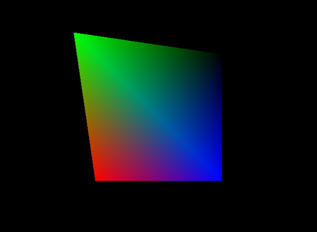
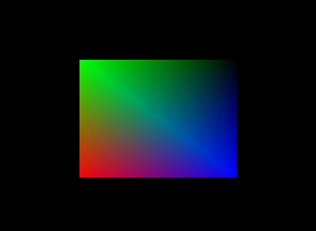
Just a reminder, but this is what the output of the program looks like as it comes out of the box:

And this is what the code for the vertices looks like (stage00.c, lines 50-55)
static Vtx shade_vtx[] =  {
        {-64,  64, -5, 0, 0, 0, 0,    0xff, 0,    0xff	}, // Top left, Green
        {64,  64, -5, 0, 0, 0, 0,    0,    0,    0xff	}, // Top right, Black
        {64, -64, -5, 0, 0, 0, 0,    0,    0xff, 0xff	}, // Bottom right, Blue
        {-64, -64, -5, 0, 0, 0, 0xff, 0,    0,    0xff	}, // Bottom left, Red
};
Code analysis
Besides the opening and closing lines, you’ll see that there are four almost identical lines, each representing a vertex. The commas separate values, and are labelled as such:
{x,	y,	z,	f,	t,	c,	r,	g,	b,	a}
{64,	64,	-5,	0,	0,	0,	0,	0xff,	0,	0xff}
- x: Coordinate for the x-axis (left-right)
- y: Coordinate for the y-axis (down-up)
- z: Coordinate for the z-axis (front-back)
- f: Flags (unused)
- t: Texture x-coordinate
- c: Texture y-coordinate
- r: Red colour hex code
- g: Green colour hex code
- b: Blue colour hex code
- a: Alpha/transparency hex code
Note: In the case of nu0, the origin is in the centre of the screen. The range for x is -160 to +160, y is -120 to +120 and z is 1 to 10 (0 is the position of the camera).
Changing coordinates
{-86, 86, -5, 0, 0, 0, 0, 0xff, 0, 0xff}, // Top left, Green
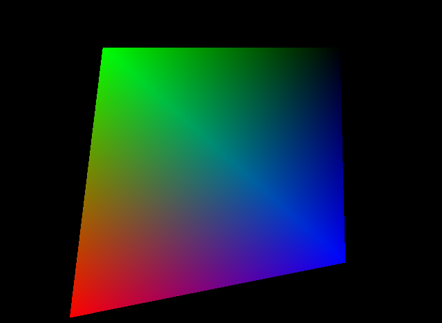
The first test we’ll go through is changing the x, y and z coordinates of the square. Let’s change the first vertex to this, and we get this result:
The output stretches the top left corner away from the axis by 50%
{-254, 254, -5, 0, 0, 0, 0, 0xff, 0, 0xff} // top-left, green
We can stretch it even further, beyond the screen:
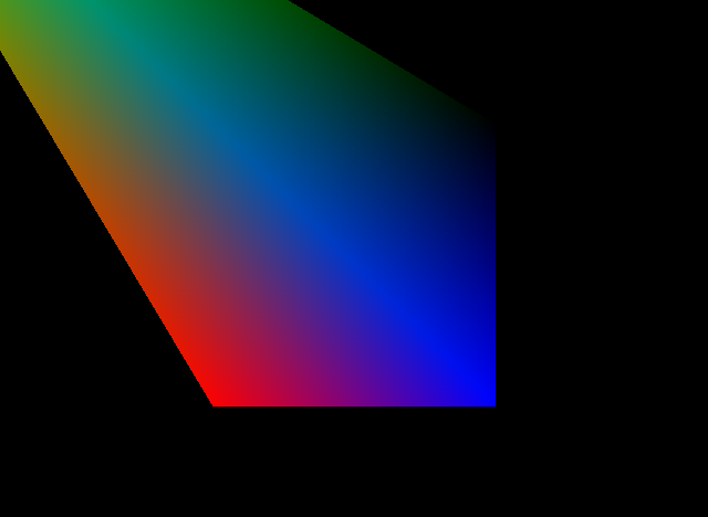
You can also assign values to the other vertices as well:
Stretching them out further
        {        -SCREEN_WD/4,  SCREEN_HT/4, -5, 0, 0, 0, 0, 0xff, 0, 0xff	},
        {         SCREEN_WD/4,  SCREEN_HT/4, -5, 0, 0, 0, 0, 0, 0, 0xff	},
        {         SCREEN_WD/4, -SCREEN_HT/4, -5, 0, 0, 0, 0, 0, 0xff, 0xff	},
        {        -SCREEN_WD/4, -SCREEN_HT/4, -5, 0, 0, 0, 0xff, 0, 0, 0xff	},
You can also use constants/variables like so.
Using SCREEN_WD and SCREEN_HT to determine coordinates.
{-84, -84, -5, 0, 0, 0, 0, 0, 0, 0xff} // 2nd vertex
You can even send one corner off to overlap another one.
{-64, 64, -10, 0, 0, 0, 0, 0xff, 0, 0xff} // top left further back, green
Let’s push the z-coordinate a bit further back. Now I know that this result looks identical to the original, but trust me, the green corner is further back. You just can’t tell because of the perspective of the camera.
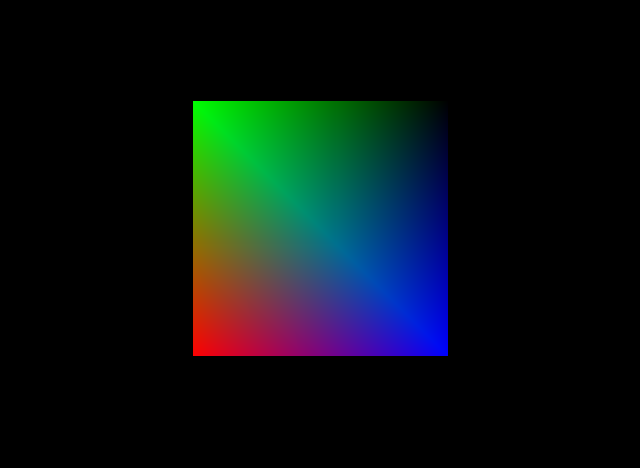
Looks identical, doesn’t it?
{ -64, 64, -20, 0, 0, 0, 0, 0xff, 0, 0xff } // top left even further back, green
But now let’s try pushing it further back. Notice that the corner disappeared. This is because it has moved so far back that it has escaped the clipping area and the pixels beyond that point are no longer displayed. Another way to imagine this is that the green corner has moved beyond the ‘wall’ at the back of the scene, so any points behind it are no longer displayed.

The green corner disappeared into the black ‘background wall’.
Texture coordinates
There are no textures involved in nu0, so we’ll skip over it for the time being.
Colour and alpha
The last four entries for each vertex are the colours, here described as a hexadecimal value between 0 and FF (255)
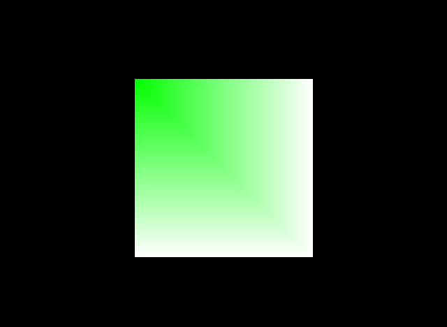
{-64, 64, -5, 0, 0, 0, 0xff, 0xff, 0xff, 0xff} // White, top-left

        {        -64,  64, -5, 0, 0, 0, 0, 0xff, 0, 0xff	}, // green, top left
        {         64,  64, -5, 0, 0, 0, 0xff, 0xff, 0xff, 0xff	}, // white, top right
        {         64, -64, -5, 0, 0, 0, 0xff, 0xff, 0xff, 0xff	}, // white, bottom right
        {        -64, -64, -5, 0, 0, 0, 0xff, 0xff, 0xff, 0xff	}  // white, bottom left
You can do it with all the other vertices too.
{ -64, 64, -5, 0, 0, 0, 0, 0xff, 0, 0 } // green, transparent, top-left
Now let’s take that same square and give it an alpha value of 0 in the top left. It won’t work because the fill mode is set to opaque. We’re going to need to change some other lines.
gDPSetRenderMode(glistp++,G_RM_AA_OPA_SURF, G_RM_AA_OPA_SURF2); // G_RM_AA_OPA_SURF is for opaque

// on line 69 change to:

gDPSetRenderMode(glistp++,G_RM_AA_XLU_SURF, G_RM_AA_XLU_SURF2); // G_RM_AA_XLU_SURF is for translucent
This will change the rendering mode for our polygons from opaque to translucent, making the top left corner fade into the background colour (black). Note that in the long run this is a more complicated render so avoid using it unless completely necessary.

Adding more triangles
This is where things get even more complicated. If you add another vertex like so, you won’t get any change, we need to add something more:
static Vtx shade_vtx[] =  {
        {-64,  64, -5, 0, 0, 0, 0,    0xff, 0,    0xff	}, // Top left, Green
        {64,  64, -5, 0, 0, 0, 0,    0,    0,    0xff	}, // Top right, Black
        {64, -64, -5, 0, 0, 0, 0,    0,    0xff, 0xff	}, // Bottom right, Blue
        {-64, -64, -5, 0, 0, 0, 0xff, 0,    0,    0xff	}, // Bottom left, Red
        {0, 100, -5, 0, 0, 0, 0xff, 0xff,    0xff,    0xff	}, // Top centre, White
};
We need to change the array on the display list to include the amount of vertices in the shade_vtx array. So we need to change this line to add a higher limit for number of vertices in the display list:
gSPVertex(glistp++,&(shade_vtx[0]),4, 0);

// line 65 change to:

gSPVertex(glistp++,&(shade_vtx[0]),5, 0);
And then we need to add another order to the display list to make another triangle:
gSP2Triangles(glistp++,0,1,2,0,0,2,3,0);

// line 72 add after:

gSP1Triangle(glistp++,0,1,4,0);
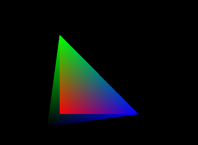
And all that should give the following result:

Putting it all together
In this mini-tutorial, we’ve gone through the following:
- The vertex array and what each value means
- Moving around x, y and z coordinates for the vertices
- Changing the colour of each vertex
- adding new vertices and using them to form new triangles
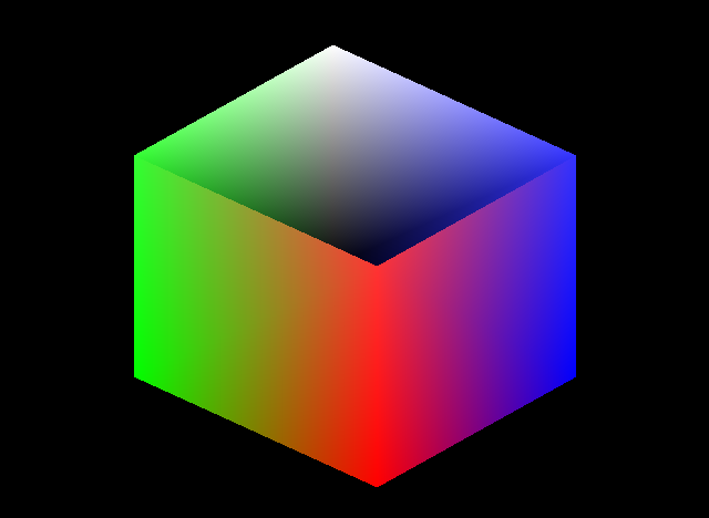
And when putting it all together we can make the following using the Nintendo 64 SDK (you should know which lines to replace by now):
static Vtx shade_vtx[] =  {

        // Top 4

        {        -100,  50, -5, 0, 0, 0, 0x33, 0xff, 0x33, 0xff	},
        {         -10,  100, -5, 0, 0, 0, 0xff, 0xff, 0xff, 0xff	},
        {         100, 50, -5, 0, 0, 0, 0x33, 0x33, 0xff, 0xff	},
        {        10, 0, -5, 0, 0, 0, 0xff, 0x33, 0x33, 0xff	},

        // Bottom 4

        {        -100,  -50, -5, 0, 0, 0, 0, 0xff, 0, 0xff	},
        {         -10,  0, -5, 0, 0, 0, 0, 0, 0, 0xff	},
        {         100, -50, -5, 0, 0, 0, 0, 0, 0xff, 0xff	},
        {        10, -100, -5, 0, 0, 0, 0xff, 0, 0, 0xff	},
};

        // Vertex array length
        gSPVertex(glistp++,&(shade_vtx[0]),8, 0);

        // Draw triangles
        // Back side
        gSP2Triangles(glistp++,0,1,5,0,5,2,6,0);
        gSP1Triangle(glistp++,1,5,2,0);

        // Front side
        gSP2Triangles(glistp++,0,3,4,0,3,4,7,0);
        gSP2Triangles(glistp++,3,2,6,0,3,6,7,0);
And this is the result from editing the code above into Nu0’s stage00.c:
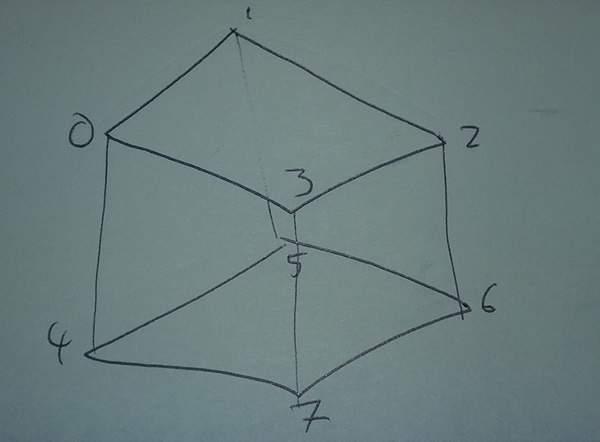
And here is a note I made to help remember where to use the gSP2Triangles by noting the index of each vertex:
So those were a few notes on how you can modify this demo to make some static graphics. Have a go and comment below with any work you’ve done using these tips.