Nu0: Starting a N64 program using NuSystem

In this article, I will explain the basics of running a Nintendo 64 program using NuSystem. The Nu0 demo used for this program is found in the following directory after creating the development environment:
C:\nintendo\n64kit\nusys\sample\nu0
This is the simplest of all the demos that you’ll find on the SDK. All it does is use NuSystem to boot up the Nintendo 64, its operating systems and everything that is dependent on it in order to display a square.
This is going to be a long article since we’ll be covering all the basics of how NuSystem and N64 environments are made using the nu0 demo. I’ll be covering the other demos included in the devkit, but this page about nu0 will contain all you need to know about the basic structure of a program.
What Nu0 does
- Loads up NuSystem
- Creates custom functions, typedefs and constants
- Enter the main process and create stage00
- Create display lists for intialising the RSP and the RDP
- Create a callback function (stage00)
- Draws a square with a colour at each corner
- Adds it to the display list to shade it in
- Enter endless loop/crash the program
Nu0 structure
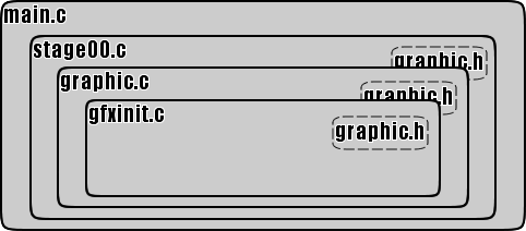
The way the files are referenced to each other can be seen in the diagram above. main.c is the main structure of the program, which calls back stage00.c. This then tries to initialise the RCP by using a function in graphic.c. That function calls two display lists (one for each processor) which were found in gfxinit.c. Most of the actual action is defined in stage00.c, everything else is just setting the ‘shell’ for the nu0 application.
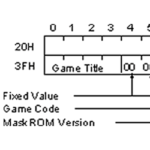
Program output
After compiling the program, you should get a file called nu0.n64 that looks like this:
Files included
- main.c – Main routine/Structure of game processing
- graphic.h – Defines some essential variables, constants and typedefs.
- gfxinit.c – Creates display lists to initialise the RSP & RDP, and defines the viewport.
- graphic.c – Creates functions to initialise the RCP and clear the frame buffer
- stage00.c – Create DL/Display processing and game processing
- Makefile/.dos/.irix – At the point of compilation, the makefile is what draws all the rules to bring the files together to make the final .n64 ROM.
- spec – Spec file for makerom
- readme.txt – This is a brief description of what the file does.
Note: After compiling you will find a whole bunch of files in the folder. This is what they do:
- .o files: These are output files, you’ll find one corresponding to each .c file. These are temporary files used during the compilation process. They’re pretty much useless once you get your .n64 file so you can ignore them.
- .out file: This is a debugger symbol file. I’m not too sure what it does or how to use it so ignore it.
- .n64 file: This is your final ROM.
What each of the files do
This section will go through the above files and explain what each bit does.
main.c
This is the main routine and structure of game processing. It’s what sets the main process, loads up nusystem, and brings up stage00.c, which is where most of the action takes place.
Code
#include <nusys.h>
void stage00(int);
void makeDL00(void);
void mainproc(void){
	nuGfxInit();
	nuGfxFuncSet((NUGfxFunc)stage00);
	nuGfxDisplayOn();
	while(1)
		;
}
void stage00(int pendingGfx) {
	if(pendingGfx < 1)
		makeDL00();
}
Line by line
#include <nusys.h>
This #include function loads up the NuSystem library to let the program reference any functions, constants, etc.
void stage00(int);
void makeDL00(void);
These two lines declare function prototypes for use later in the program.
void mainproc(void){} is the main function, where all the action happens.
nuGfxInit(); kick-starts the graphics engine.
nuGfxFuncSet((NUGfxFunc)stage00); is a bit more complicated to explain so let’s go bit by bit. stage00 up until this point was a blank function with no input and no output (void). What this line does is that it gives the stage00 function an output type (NUGfxFunc) an then registers it as the callback function. The stage00 function will be called back every time the screen refreshes.
nuGfxDisplayOn(); turns on the screen. Really that simple.
while(1)
; This enters an infinite loop. More simply, it just crashes the program, preventing it from doing anything else beyond this point.
void stage00(int pendingGfx){[Some code here]} This defines the stage00 function, with one integer as input.
if(pendingGfx < 1)
makeDL00(); This checks for the amount of graphics tasks set, and if there are none, it runs the makeDL00 function from the stage00.c file.
graphic.h
This file defines several different things like constants, variables, typedefs, display lists and some function prototypes that are used in most of the other files in the the application.
Code
#ifndef _GRAPHIC_H_
#define _GRAPHIC_H_
#define SCREEN_HT        240
#define SCREEN_WD        320
#define GFX_GLIST_LEN     2048
typedef struct {
  Mtx     projection;
  Mtx     modeling;
} Dynamic;
extern Dynamic gfx_dynamic;
extern Gfx* glistp;
extern Gfx gfx_glist[GFX_GLIST_LEN];
extern void gfxRCPInit(void);
extern void gfxClearCfb(void);
extern Gfx setup_rdpstate[];
extern Gfx setup_rspstate[];
#endif
Line by Line
#ifndef _GRAPHIC_H_, #define _GRAPHIC_H_ and #endif at the end make it so that the code in this file is only run once.
#define SCREEN_HT 240 and #define SCREEN_WD 320 define two constants, later to be used for defining the viewport, orthogonal projection and graphic.c.
#define GFX_GLIST_LEN 2048 is used to define the size of a display list array later on.
typedef struct {Mtx projection; Mtx modeling;} Dynamic; sets a new type definition called Dynamic which contains two 4×4 transformation matrices, one for projection and one for modeling.
extern Dynamic gfx_dynamic; declare a variable as the type that was just defined in the previous line.
extern Gfx gfx_glist[GFX_GLIST_LEN]; opens an array which will act as our display list for later on in the program.
extern void gfxRCPInit(void); and extern void gfxClearCfb(void); set two function prototypes for later use in graphic.c
extern Gfx setup_rdpstate[]; and extern Gfx setup_rspstate[]; similarly just define arrays for use in gfxinit.c.
graphic.c
This file is quite simple in that it only does a few things – it creates a function to run the display lists that initialise the RSP & RDP, and creates another one that clears the frame buffer.
code
#include
#include "graphic.h"
Gfx          gfx_glist[GFX_GLIST_LEN];
Dynamic      gfx_dynamic;
Gfx*         glistp;
void gfxRCPInit(void) {
  gSPSegment(glistp++, 0, 0x0);
  gSPDisplayList(glistp++, OS_K0_TO_PHYSICAL(setup_rspstate));
  gSPDisplayList(glistp++, OS_K0_TO_PHYSICAL(setup_rdpstate));
}
void gfxClearCfb(void) {
  gDPSetDepthImage(glistp++, OS_K0_TO_PHYSICAL(nuGfxZBuffer));
  gDPSetCycleType(glistp++, G_CYC_FILL);
  gDPSetColorImage(glistp++, G_IM_FMT_RGBA, G_IM_SIZ_16b,SCREEN_WD, OS_K0_TO_PHYSICAL(nuGfxZBuffer));
  gDPSetFillColor(glistp++,(GPACK_ZDZ(G_MAXFBZ,0) << 16 | GPACK_ZDZ(G_MAXFBZ,0)));
  gDPFillRectangle(glistp++, 0, 0, SCREEN_WD-1, SCREEN_HT-1);
  gDPPipeSync(glistp++);
  gDPSetColorImage(glistp++, G_IM_FMT_RGBA, G_IM_SIZ_16b, SCREEN_WD, osVirtualToPhysical(nuGfxCfb_ptr));
  gDPSetFillColor(glistp++, (GPACK_RGBA5551(0, 0, 0, 1) << 16 | GPACK_RGBA5551(0, 0, 0, 1)));
  gDPFillRectangle(glistp++, 0, 0, SCREEN_WD-1, SCREEN_HT-1);
  gDPPipeSync(glistp++);
}
Line by Line
#include <nusys.h> Same old includes.
Gfx gfx_glist[GFX_GLIST_LEN];, Dynamic gfx_dynamic; and Gfx* glistp; define the display list, the dynamic matrix and the display list pointer respectively.
void gfxRCPInit(void) {} takes the function prototype from the header.h file and defines it.
gSPSegment(glistp++, 0, 0x0); sets the address of the segment.
gSPDisplayList(glistp++, OS_K0_TO_PHYSICAL(setup_rspstate)); and gSPDisplayList(glistp++, OS_K0_TO_PHYSICAL(setup_rdpstate)); These two lines add a child display list to the glistp display list. OS_K0_TO_PHYSICAL() converts the virtual address of the array into a physical address.
void gfxClearCfb(void) {} is another custom function for nu0 that is made to clear the frame buffer.
gDPSetDepthImage(glistp++, OS_K0_TO_PHYSICAL(nuGfxZBuffer)); sets the z-buffer to be the standard NuSystem z-buffer.
gDPSetCycleType(glistp++, G_CYC_FILL); Sets the RDP’s cycle mode to Fill.
gDPSetColorImage(glistp++, G_IM_FMT_RGBA, G_IM_SIZ_16b,SCREEN_WD, OS_K0_TO_PHYSICAL(nuGfxZBuffer)); is one of thsoe complicated ones… gDPSetColorImage sets the colour mode for the RDP. G_IM_FMT_RGBA means that it will use Red/Green/Blue/Alpha colours, G_IM_SIZ_16b means that it will use a 16-bit colour rather than 32-bit, SCREEN_WD is the image width, set to the max width we’re using and OS_K0_TO_PHYSICAL(nuGfxZBuffer) is the physical location of the z-buffer.
gDPSetFillColor(glistp++,(GPACK_ZDZ(G_MAXFBZ,0) << 16 | GPACK_ZDZ(G_MAXFBZ,0))); clears the z-buffer by filling it with the max value.
gDPFillRectangle(glistp++, 0, 0, SCREEN_WD-1, SCREEN_HT-1); fills in the space of the entire screen with the colour defined in the previous line. In this case that is the screen wiper.
gDPPipeSync(glistp++); Ensures that the pixels rendered are from the correct cycle type, in case the processor switches to a different cycle type.
The rest of this code is a rehash of the previous few lines, except that this clears the frame buffer instead of the z-buffer.
gfxinit.c
This file creates a static display list to initialise each of the two processors in the RCP as well as creating a viewport to see the scene through.
code
#include <nusys.h>
#include "graphic.h"
static Vp vp = {
    SCREEN_WD*2, SCREEN_HT*2, G_MAXZ/2, 0,
    SCREEN_WD*2, SCREEN_HT*2, G_MAXZ/2, 0,
};
Gfx setup_rdpstate[] = {
  gsDPSetRenderMode(G_RM_OPA_SURF, G_RM_OPA_SURF2),
  gsDPSetCombineMode(G_CC_SHADE, G_CC_SHADE),
  gsDPSetScissor(G_SC_NON_INTERLACE, 0,0, SCREEN_WD,SCREEN_HT),
  gsDPSetColorDither(G_CD_BAYER),
  gsSPEndDisplayList(),
};
Gfx setup_rspstate[] = {
  gsSPViewport(&vp),
  gsSPClearGeometryMode(0xFFFFFFFF),
  gsSPSetGeometryMode(G_ZBUFFER | G_SHADE | G_SHADING_SMOOTH | G_CULL_BACK),
  gsSPTexture(0, 0, 0, 0, G_OFF),
  gsSPEndDisplayList(),
};
Line by Line
#include are the includes. Standard stuff.
static Vp vp = {} sets the viewport. The viewport is the ‘window’ in which you view a 3D environment. a full explanation of how this works can be found on the type definitions page.
Gfx setup_rdpstate[] = {} and Gfx setup_rspstate[] = {} sets the array for the settings for the RDP and the RSP for alter use in graphic.c. Note that all of the functions used use gsDP instead of gDP which means that we’re setting a display list rather than adding to one that was already created.
gsDPSetRenderMode(G_RM_OPA_SURF, G_RM_OPA_SURF2) sets the render mode to make opaque surfaces.
gsDPSetCombineMode(G_CC_SHADE, G_CC_SHADE) sets the colour combiner mode, in this case to G_CC_SHADE. What this means is that it sets the output colour to the shade colour and nothing else (excluding lighting, shade, fog and translucent objects).
gsDPSetScissor(G_SC_NON_INTERLACE, 0,0,SCREEN_WD,SCREEN_HT) is used to remove pixels from outside the drawing region to help speed up processing. G_SC_NON_INTERLACE means to do all the scanlines, and 0,0,SCREEN_WD,SCREEN_HT defines the size of the screen.
gsDPSetColorDither(G_CD_BAYER) sets the dither method, this one is using the Bayer method but others are available.
gsSPViewport(&vp) sets the viewport t what was defined in the previous static Vp vp = {} line.
gsSPClearGeometryMode(0xFFFFFFFF) resets the geometry mode.
gsSPSetGeometryMode(G_ZBUFFER | G_SHADE | G_SHADING_SMOOTH | G_CULL_BACK) sets a new geometry mode: G_ZBUFFER enables z-buffer calculations, G_SHADE enables vertex colours for triangles, G_SHADING_SMOOTH enables Gouraud shading and G_CULL_BACK allows for back-face culling.
gsSPTexture(0, 0, 0, 0, G_OFF) turns off textures.
gsSPEndDisplayList() ends the display list.
stage00.c
This is where the meat of the program is. It brings together everything that was previously included in graphic.c and gfxinit.c to finally start the processors and clear the frame buffer.
Code
#include <assert.h>
#include <nusys.h>
#include "graphic.h"
void shadetri(Dynamic* dynamicp);
void makeDL00(void){
  glistp = gfx_glist;
  gfxRCPInit();
  gfxClearCfb();
  guOrtho(&gfx_dynamic.projection,
	  -(float)SCREEN_WD/2.0F, (float)SCREEN_WD/2.0F,
	  -(float)SCREEN_HT/2.0F, (float)SCREEN_HT/2.0F,
	  1.0F, 10.0F, 1.0F);
  guRotate(&gfx_dynamic.modeling, 0.0F, 0.0F, 0.0F, 1.0F);
  shadetri(&gfx_dynamic);
  gDPFullSync(glistp++);
  gSPEndDisplayList(glistp++);
  assert(glistp - gfx_glist < GFX_GLIST_LEN); nuGfxTaskStart(gfx_glist, (s32)(glistp - gfx_glist) * sizeof (Gfx), NU_GFX_UCODE_F3DEX , NU_SC_SWAPBUFFER); } static Vtx shade_vtx[] = { { -64, 64, -5, 0, 0, 0, 0, 0xff, 0, 0xff }, { 64, 64, -5, 0, 0, 0, 0, 0, 0, 0xff }, { 64, -64, -5, 0, 0, 0, 0, 0, 0xff, 0xff }, { -64, -64, -5, 0, 0, 0, 0xff, 0, 0, 0xff }, }; void shadetri(Dynamic* dynamicp) { gSPMatrix(glistp++,OS_K0_TO_PHYSICAL(&(dynamicp->projection)),
		G_MTX_PROJECTION|G_MTX_LOAD|G_MTX_NOPUSH);
  gSPMatrix(glistp++,OS_K0_TO_PHYSICAL(&(dynamicp->modeling)),
		G_MTX_MODELVIEW|G_MTX_LOAD|G_MTX_NOPUSH);
  gSPVertex(glistp++,&(shade_vtx[0]),4, 0);
  gDPPipeSync(glistp++);
  gDPSetCycleType(glistp++,G_CYC_1CYCLE);
  gDPSetRenderMode(glistp++,G_RM_AA_OPA_SURF, G_RM_AA_OPA_SURF2);
  gSPClearGeometryMode(glistp++,0xFFFFFFFF);
  gSPSetGeometryMode(glistp++,G_SHADE| G_SHADING_SMOOTH);
  gSP2Triangles(glistp++,0,1,2,0,0,2,3,0);
}
Line by line
#include <assert.h>
#include <nusys.h>
#include "graphic.h" Just some includes.
void shadetri(Dynamic* dynamicp); Function prototype for shadetri function. Dynamic is defined in graphic.h and *dynamicp is a pointer to the polygon array that will display the square in the ROM.
void makeDL00(void){} This declares the content of the makeDL00 function from main.c.
glistp = gfx_glist; records the pointer of the display list buffer. This an an array derived from gfx_glist[GFX_GLIST_LEN] in the graphic.h file.
gfxRCPInit(); initialises the RCP (Reality CoProcessor).
gfxClearCfb(); clears the frame buffer and z-buffer.
guOrtho(&gfx_dynamic.projection, -(float)SCREEN_WD/2.0F, (float)SCREEN_WD/2.0F, -(float)SCREEN_HT/2.0F, (float)SCREEN_HT/2.0F, 1.0F, 10.0F, 1.0F); his one is a bit complicated so bear with me. guOrtho is a function that creates an orthogonal projection matrix and saves it into its first argument. An orthogonal projection is what you get when you take a 3D object and flatten it so that it makes a 2D image that can later be used to display on a screen, similar to how a camera takes a snapshot of a scene and flattens it onto a picture. &gfx_dynamic.projection is the variable where it is stored (var and typedef defined in graphic.h), the next four variables like (float)SCREEN_XX/2.0F define the coordinates of the projection area, 1.0F and 10.0F define the near and far clipping plane (area which any polygons that are beyond will not be shown) and finally the last 1.0F determines the sale, which is 1 so it does nothing.
guRotate(&gfx_dynamic.modeling, 0.0F, 0.0F, 0.0F, 1.0F); prepares an axis to allow the rotation of the projection. The rotation is of 0 degrees (the 1st 0.0F) about the Z axis (0.0F, 0.0F, 1.0F)
shadetri(&gfx_dynamic); applies the shadetri function (declared in the beginning of this file and defined at the end) to the graphics defined in the previous two lines and draws a square.
gDPFullSync(glistp++); tells the RDP (Reality Display Processor) that the final command in the display list has been completed.
Note that these two likes contain glistp++, which increments glistp for every time it runs.
gSPEndDisplayList(glistp++); ends the display list.
assert(glistp - gfx_glist < GFX_GLIST_LEN); compares the length of the display list to the max length determined in the graphic.h file. If it is too long, that means that there is a GBI command written outside of the array, making the program crash and display an error.
nuGfxTaskStart(gfx_glist, (s32)(glistp - gfx_glist) * sizeof (Gfx), NU_GFX_UCODE_F3DEX , NU_SC_SWAPBUFFER); This is another complicated one. nuGfxTaskStart is a function that starts the Reality Signal Processor (RSP) task. gfx_glist is the pointer to the start of the display list that will be worked on. (s32)(glistp - gfx_glist) * sizeof (Gfx) is the size of the display list: (glistp - gfx_glist) is the amount of items in the list multiplied by sizeof (Gfx), which is the size of the items. NU_GFX_UCODE_F3DEX is the name of the microcode to be used and NU_SC_SWAPBUFFER is a flag that swaps the back and front frame buffer so that a new frame can appear.
static Vtx shade_vtx[] = {}; declares the shade_vtx array, which are the different vertices of the square. This is what each value of {x, y, z, f, t, c, r, g, b, a} means: x, y, z, are the coordinates of the vector, f is for flags (unused), t, c are the texture coordinates and r, g, b, a are the red/green/blue/alpha (transparency) values for the colour of the vertex.
void shadetri(Dynamic* dynamicp){} defines the function that will shade our square. The code within shadetri doesn’t use any NuSystem functions, only N64OS functions and constants.
gSPMatrix(glistp++,OS_K0_TO_PHYSICAL(&(dynamicp->projection)),G_MTX_PROJECTION|G_MTX_LOAD|G_MTX_NOPUSH); is another complicated one. gSPMatrix is a function that inserts matrix operations into the display list. This (I think) means that that it takes the display list and adds a matrix to it based on the rest of the parameters. glistp++ is the display list pointer (plus one for the new location), OS_K0_TO_PHYSICAL takes a cached (KSEG0) CPU virtual address (in this case &(dynamicp->projection), which is the orthographic projection defined in the guOrtho line earlier) to a physical address. The rest of this line are flags, G_MTX_PROJECTION tells it that this is a projection matrix, G_MTX_LOAD loads the matrix to the top and G_MTX_NOPUSH doesn’t push the matrix stack before the function runs. To be honest, I don’t really understand what this all means, but I’ll get to it eventually.
gSPMatrix(glistp++,OS_K0_TO_PHYSICAL(&(dynamicp->modeling)),G_MTX_MODELVIEW|G_MTX_LOAD|G_MTX_NOPUSH); is identical to the previous line, except that it deals with the model rather then the projection.
gSPVertex(glistp++,&(shade_vtx[0]),4, 0); loads the vertices. You should get this by now, but glistp++ is the pointer to the display list. &(shade_vtx[0]) is the array of vertices which was defined in an earlier line, 4 is the number of vertices and 0 is the starting index of the vertex buffer (which vertex to start from, 0 works fine in most cases).
gDPPipeSync(glistp++); tells the RDP to wait during the rendering of primitives allowing it to sync up.
gDPSetCycleType(glistp++,G_CYC_1CYCLE); sets the RDP to 1-cycle mode. This means that it paints one pixel per cycle.
gDPSetRenderMode(glistp++,G_RM_AA_OPA_SURF, G_RM_AA_OPA_SURF2); sets the rendering mode of the blender. G_RM_AA_OPA_SURF is a setting that makes the surface render as opaque, and G_RM_AA_OPA_SURF2 is the same thing, but a second time.
gSPClearGeometryMode(glistp++,0xFFFFFFFF); This line is a bit bizarre… The point of it is to reset the geometry mode, and the first argument is the display list (as usual), but the second argument is a hex code for what I think is a colour, when it’s supposed to be a mode (eg G_SHADE or G_ZBUFFER). Don’t know what this argument means, maybe it’s a colour, maybe it just means ‘blank’ or maybe it’s related to the next line.
gSPSetGeometryMode(glistp++,G_SHADE| G_SHADING_SMOOTH); This sets the geometry mode for the display list. In this case, G_SHADE calculates the colour and G_SHADING_SMOOTH does the Gouraud shading for the vertex.
gSP2Triangles(glistp++,0,1,2,0,0,2,3,0); is what draws the two triangles. glistp++ is the display list, 0,1,2,0 and 0,2,3,0 are the two triangles, the first three numbers of each section (0,1,2 and 0,2,3) are the vertices for our two triangles and the last 0 is the flag, meaning that there is no flag.
Makefile
There are three makefiles: Makefile, Makefile.dos and Makefile.irix. Kinda obvious, but you’re going to want to ignore the .dos and .irix since those are for MS DOS and SGI workstations respectively, and we will be using the gcc makefile (without file extension).
Code
include $(ROOT)/usr/include/make/PRdefs
N64KITDIR = c:\nintendo\n64kit
NUSYSINCDIR = $(N64KITDIR)/nusys/include
NUSYSLIBDIR = $(N64KITDIR)/nusys/lib
LIB = $(ROOT)/usr/lib
LPR = $(LIB)/PR
INC = $(ROOT)/usr/include
CC = gcc
LD = ld
MAKEROM = mild
LCDEFS = -DNU_DEBUG -DF3DEX_GBI_2
LCINCS = -I. -I$(NUSYSINCDIR) -I$(ROOT)/usr/include/PR
LCOPTS = -G 0
LDFLAGS = $(MKDEPOPT) -L$(LIB) -L$(NUSYSLIBDIR) -lnusys_d -lgultra_d -L$(GCCDIR)/mipse/lib -lkmc
OPTIMIZER = -g
APP = nu0.out
TARGETS = nu0.n64
HFILES = graphic.h
CODEFILES = main.c stage00.c graphic.c gfxinit.c
CODEOBJECTS = $(CODEFILES:.c=.o) $(NUSYSLIBDIR)/nusys.o
DATAFILES =
DATAOBJECTS = $(DATAFILES:.c=.o)
CODESEGMENT = codesegment.o
OBJECTS = $(CODESEGMENT) $(DATAOBJECTS)
default: $(TARGETS)
include $(COMMONRULES)
$(CODESEGMENT): $(CODEOBJECTS) Makefile
$(LD) -o $(CODESEGMENT) -r $(CODEOBJECTS) $(LDFLAGS)
$(TARGETS): $(OBJECTS)
$(MAKEROM) spec -I$(NUSYSINCDIR) -r $(TARGETS) -e $(APP)
Line by line
include $(ROOT)/usr/include/make/PRdefs Includes another file in this one. The file has what I assume is some standard makefile settings. Some of these settings are also in the makefile itself, so you can override these defaults if you want. Note: this line grabs $(ROOT) from c:\make.bat (or whatever you called it) so keep this in mind if you are using different folders.
N64KITDIR = c:\nintendo\n64kit, NUSYSINCDIR = $(N64KITDIR)/nusys/include and NUSYSLIBDIR = $(N64KITDIR)/nusys/li: these define some variables for ease of use later on. Note: You might want to edit N64KITDIR = c:\nintendo\n64kit to a the directory you’re using if it’s not the default.
LIB = $(ROOT)/usr/lib, LPR = $(LIB)/PR and INC = $(ROOT)/usr/include set the location of the libraries referenced for later use.
CC = gcc means “The C Compiler is the GNU Compiler Collection” which is the name of the C Compiler
LD = ld sets the link editor name.
MAKEROM = mild: This specifies the ROM creation tool.
LCDEFS = -DNU_DEBUG -DF3DEX_GBI_2, LCINCS = -I. -I$(NUSYSINCDIR) -I$(ROOT)/usr/include/PR, LCOPTS = -G 0 are as of now unknown. They are just variables to be used as part of the CFLAGS setting, from the file included in the first line of the makefile. These settings are used for optimising the ROM.
LDFLAGS = $(MKDEPOPT) -L$(LIB) -L$(NUSYSLIBDIR) -lnusys_d -lgultra_d -L$(GCCDIR)/mipse/lib -lkmc Much like CFLAGS, these are just a list of settings, just that they’re used for the link editor instead of the optimiser.
OPTIMIZER = -g Most likely used as another way of optimising the CFLAGS somewhere in the code.
APP = nu0.out specifies the debug output file.
TARGETS = nu0.n64 specifies the variable for the name of the ROM file.
HFILES = graphic.h names the header files for this specific makefile.
CODEFILES = main.c stage00.c graphic.c gfxinit.c These are all the .c files that will be compiled.
CODEOBJECTS = $(CODEFILES:.c=.o) $(NUSYSLIBDIR)/nusys.o creates .o (object) files for each .c file mentioned in the previous line.
DATAFILES = Empty setting 🙁
DATAOBJECTS = $(DATAFILES:.c=.o) converts files in the previous line into .o files. Since it’s empty, this line does nothing.
CODESEGMENT = codesegment.o secifies the relocationable object file name created as a result of linking the program code.
OBJECTS = $(CODESEGMENT) $(DATAOBJECTS) joins the two previous lines to make a list of object files.
default: $(TARGETS) As mentioned above in the TARGETS = nu0.n64 line, this just sets the variable as the output of the makefile.
include $(COMMONRULES): Unknown
$(CODESEGMENT): $(CODEOBJECTS) Makefile This tells the makefile to establish a relation between codesegment.o, the individual .o files in the project.
$(LD) -o $(CODESEGMENT) -r $(CODEOBJECTS) $(LDFLAGS) This uses the linker to link the .o files together to then output into codesegment.o.
$(TARGETS):$(OBJECTS) This links the target (the ROM, nu0.n64) with the .o files.
$(MAKEROM) spec -I$(NUSYSINCDIR) -r $(TARGETS) -e $(APP) is the line that builds the ROM. $(MAKEROM) (aka mild, remember?) is the rom creation tool used, spec loads up the spec file, -I$(NUSYSINCDIR) shows the directory for including NuSystem files, -r $(TARGETS) is the filename for the ROM and finally -e $(APP) creates the debug symbol file (.out).
And that’s what the Makefile file does: it brings all the files together to initiate the compilation of out nu0 program.
Spec file
The purpose of the specfile is to define segments of code. Running the entire program at once is very hard on the memory but if it is divided into smaller chunks, the game will run more smoothly. Like the makefile, the Spec file has no file extension but can be edited with a text editor like Notepad.
Code
#include <nusys.h>

beginseg
	name	"code"
	flags	BOOT OBJECT
	entry 	nuBoot
	address NU_SPEC_BOOT_ADDR
        stack   NU_SPEC_BOOT_STACK
	include "codesegment.o"
	include "$(ROOT)/usr/lib/PR/rspboot.o"
	include "$(ROOT)/usr/lib/PR/gspF3DEX2.fifo.o"
	include "$(ROOT)/usr/lib/PR/gspL3DEX2.fifo.o"
	include "$(ROOT)/usr/lib/PR/gspF3DEX2.Rej.fifo.o"
        include "$(ROOT)/usr/lib/PR/gspF3DEX2.NoN.fifo.o"
        include "$(ROOT)/usr/lib/PR/gspF3DLX2.Rej.fifo.o"
	include "$(ROOT)/usr/lib/PR/gspS2DEX2.fifo.o"
endseg

beginwave
	name	"nu0"
	include	"code"
endwave
Line by line
beginseg Initiates the process of defining segments.
name "code" defines the name of the segments
flags BOOT OBJECT designates the boot object
entry nuBoot specifies the boot function
address NU_SPEC_BOOT_ADDR Not too sure about this one, but I guess it sets the physical address for that segment (default 0x80025c00).
stack NU_SPEC_BOOT_STACK defines the stack (temp memory) size for the segment (default 0x2000).
include "codesegment.o" specifies the object file mapping used by the boot function.
include "$(ROOT)/usr/lib/PR/gspF3DEX2.fifo.o", include "$(ROOT)/usr/lib/PR/gspL3DEX2.fifo.o", include "$(ROOT)/usr/lib/PR/gspF3DEX2.Rej.fifo.o", include "$(ROOT)/usr/lib/PR/gspF3DEX2.NoN.fifo.o", include "$(ROOT)/usr/lib/PR/gspF3DLX2.Rej.fifo.o", include "$(ROOT)/usr/lib/PR/gspS2DEX2.fifo.o" is thevarious microcodes used. This includes the boot microcode for the Reality Signal Processor (RSP) and the graphics.
endseg ends the definition of the segment.
beginwave endwave This section defines the wave. It brings together all the different segments defined previously in the spec file so that they can be used.
name "nu0" is the name of the wave.
include "code" is the name of the segment to be included (from the name "code" line). There can be multiple segments in a wave.
Conclusion
The Nintendo 64 doesn’t start on it’s own. It just doesn’t. You need to give it a good kickstart before anything happens.
For the next step (adding controller input and refreshing) have a look at the Nu1 page to see that sample program and its code.
To have a look at some fun with moving vertices around, have a look at the Nu0 Vertices post.